Tuesday, October 2, 2018
SPECIAL TOPIC-DEMODULATION
This a side topic on DEMODULATION, PARTICULARLY OF AM SIGNALS.
bELOW ARE THREE WAYS AND NOT NECESSARILY THE ONLY WAYS.
1. DIODE DETECTION
The most common. If we look at the original "Crystal Set" receiver, a diode converts the RF AC to DC. and sine the AC is AM, the converted DC fluctuates in accordance to the signal strength.
In Super Heterodyne radios , this technique is used.
2. Current/Voltage sensing
In regenerative receivers, a low power oscillator is the RX. When a signal of the same frequency appears, the current draw on this oscillator changes. It can be sensed by putting a transformer in series to the supply line. A secondary winding senses the fluctuating current draw.
A cap straight to the collector can also sense the voltage changes.
3. Direct Conversion
A mixer mixes the incoming signal with a local OSC where the differential is within the human hearing.
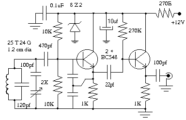 ....THIS IS THE VFO. IT CAN TUNE FROM 2.567 TO 2.667 MHZ.
Thursday, September 27, 2018
Hi Good Day! It is TGIF, Sept. 24, 2018
I would to do a write up on the concept of SSB today.
In the old days of tubes, it was explained from the pint of view of Amplitude Modulation (AM), removing the carrier wave, then one side band wave.
Well, it started that wave. Speech was introduced to carrier wave by changing the strength of the signal in accordance with the speech. The frequency remained the same. This was in fact accomplished in the final stage of the signal before leaving the antenna. an audio amp with a microphone drives a transformer when a secondary controlled the flow of current to the final stage. Without any speech, the carrier wave is stills sent and appears as a hissing sound in the receiving radio. When speech is introduced, the carrier wave as shown in an oscilloscope will appear to be changing in strength and was called an envelope.
In the receiver such as a simple Crystal receiver, a coil picks up the AC signal. a diode converts it to DC and since the original AC was changing in strength, the DSC also fluctuated in accordance to the speech. The speech is recovered.
To appreciate the modern explanation, we must first appreciate DIRECT CONVERSION receivers. In a direct conversion receiver, an incoming signal or broadcast is mixed with another frequency created by a local oscillator such that the frequency resulting falls within human hearing range. Then we can hear the speech. There is no need to convert AC to DC to derived the speech from the fluctuating DC. When we lower ther frequency of a signal to about 1.5 Khz, we can hear the speech!
To create sensitivity, we amplify the signal. To create selectivity, we use tuned rf amplifiers which allows only a certain frequency range to be amplified. We see this in our commercial AM BCB radios. In those radios, the original freq. of the signal received is mixed with a local oscillator which create a new signal at an "intermediate frequency" (455 Khz). Small transformers are used t tune in and peak at 455 Khz. The signal is amplified. In the end, it is rectified to DC with a diode. We DC follows the strength of the speech, thus we hear it.
In FM radios. the amplitude is kept fixed and the speech influences the frequency within a certain bandwidth. Same thing is done in the receiver, however, a discrimiator detects the frequency shift and converts it to moving current/voltage which is sound to us.
Now take note: in AM, the modulation is in the end stage of the TX. In FM, it is in the initial stage.
These are important backgrounds to understand SSB.
Even in tube days, a circuit was developed wherein 2 frequencies F1 and F2 were mixed. F1 would be the speech at 1.5 Khz. F2 is a selected frequency no fifferenct from the "intermediate frequency" in AM radios.
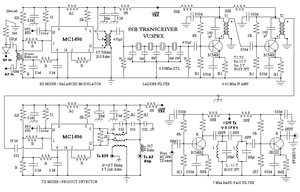
The intermediate frequency can be anything suitable for the purpose. 455 Khz was used. 12.5 Mhz is used, 10 Mhz is used. 4.43 Mhz is used. Let us take the IF to be 4.43 Mhz. The LO therefore has to be 4.43 Mhz plus 1.5 Khz. Why? so that when mixed with the speech freq. of 1.5 Khz, it cancels the 12.5 Khz leaving the freq. at 4.43 Mhz. The 4.43 Mhz signal is amplified selectively. It is then fed into another mixer, this time to raise it into a frequency at which we want to transmit. Another local oscillator is used. It is called the VFO and in this case the VFO has range where the output of the mixer is say, 7.1 Mhz or the 40 meter band.(Subtract the 4.43 from 7.1=the VFO frequency needed).
To receive at 7.1 Mhz, the signal is mixed with the VFO to net 4.43 Mhz. It is again amplifed and fed into a second mixer with a local oscillator called the BFO so that the output is 1.5 Khz which is within our hearing. The audio is amplified to drive a speaker.
Selectivity is achieved by using a filter for teh 4.43 Mhz which are 4 xtals at that frequency in series. IF transformers are also used.
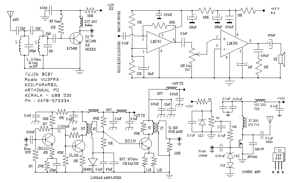
WE CAN NOW REVIEW VU3MPX SSB TRANSCEIVER CIRCUIT .
I would to do a write up on the concept of SSB today.
In the old days of tubes, it was explained from the pint of view of Amplitude Modulation (AM), removing the carrier wave, then one side band wave.
Well, it started that wave. Speech was introduced to carrier wave by changing the strength of the signal in accordance with the speech. The frequency remained the same. This was in fact accomplished in the final stage of the signal before leaving the antenna. an audio amp with a microphone drives a transformer when a secondary controlled the flow of current to the final stage. Without any speech, the carrier wave is stills sent and appears as a hissing sound in the receiving radio. When speech is introduced, the carrier wave as shown in an oscilloscope will appear to be changing in strength and was called an envelope.
In the receiver such as a simple Crystal receiver, a coil picks up the AC signal. a diode converts it to DC and since the original AC was changing in strength, the DSC also fluctuated in accordance to the speech. The speech is recovered.
To appreciate the modern explanation, we must first appreciate DIRECT CONVERSION receivers. In a direct conversion receiver, an incoming signal or broadcast is mixed with another frequency created by a local oscillator such that the frequency resulting falls within human hearing range. Then we can hear the speech. There is no need to convert AC to DC to derived the speech from the fluctuating DC. When we lower ther frequency of a signal to about 1.5 Khz, we can hear the speech!
To create sensitivity, we amplify the signal. To create selectivity, we use tuned rf amplifiers which allows only a certain frequency range to be amplified. We see this in our commercial AM BCB radios. In those radios, the original freq. of the signal received is mixed with a local oscillator which create a new signal at an "intermediate frequency" (455 Khz). Small transformers are used t tune in and peak at 455 Khz. The signal is amplified. In the end, it is rectified to DC with a diode. We DC follows the strength of the speech, thus we hear it.
In FM radios. the amplitude is kept fixed and the speech influences the frequency within a certain bandwidth. Same thing is done in the receiver, however, a discrimiator detects the frequency shift and converts it to moving current/voltage which is sound to us.
Now take note: in AM, the modulation is in the end stage of the TX. In FM, it is in the initial stage.
These are important backgrounds to understand SSB.
Even in tube days, a circuit was developed wherein 2 frequencies F1 and F2 were mixed. F1 would be the speech at 1.5 Khz. F2 is a selected frequency no fifferenct from the "intermediate frequency" in AM radios.
The intermediate frequency can be anything suitable for the purpose. 455 Khz was used. 12.5 Mhz is used, 10 Mhz is used. 4.43 Mhz is used. Let us take the IF to be 4.43 Mhz. The LO therefore has to be 4.43 Mhz plus 1.5 Khz. Why? so that when mixed with the speech freq. of 1.5 Khz, it cancels the 12.5 Khz leaving the freq. at 4.43 Mhz. The 4.43 Mhz signal is amplified selectively. It is then fed into another mixer, this time to raise it into a frequency at which we want to transmit. Another local oscillator is used. It is called the VFO and in this case the VFO has range where the output of the mixer is say, 7.1 Mhz or the 40 meter band.(Subtract the 4.43 from 7.1=the VFO frequency needed).
To receive at 7.1 Mhz, the signal is mixed with the VFO to net 4.43 Mhz. It is again amplifed and fed into a second mixer with a local oscillator called the BFO so that the output is 1.5 Khz which is within our hearing. The audio is amplified to drive a speaker.
Selectivity is achieved by using a filter for teh 4.43 Mhz which are 4 xtals at that frequency in series. IF transformers are also used.
WE CAN NOW REVIEW VU3MPX SSB TRANSCEIVER CIRCUIT .
Wednesday, September 26, 2018
Hi Good Morning friends. It is Thursday , Sept. 27. Time flies, it never lands.....In FB, Mr. Ben Naval Villoria started a group to discuss SSB. I sharing this nice circuit of VU3MPX which can be considered a modern day circuitry and simplified. It uses the MC 1496 that Motorola obviously developed for communications gear.
In regular MIXERS such as the one in the AM BCB radio, two frequencies F1 and F2 are mixed. The output in the MIXER are F1, F2, F2 + or - F2.(The original frequencies and their sum and difference).
Motorola came out with this IC where the original frequencies are cancelled out and outputs only the sum and difference. It is called a double balance modulator. Great for SSB application as the circuit of VU3MPX shows.
Subscribe to:
Posts (Atom)